Wiring the robot
Connecting it all up: the batteries, the breaker, the power distribution board, the SPARK motor controllers, the motors and the MiniCore — and which port ends up driving which wheel.
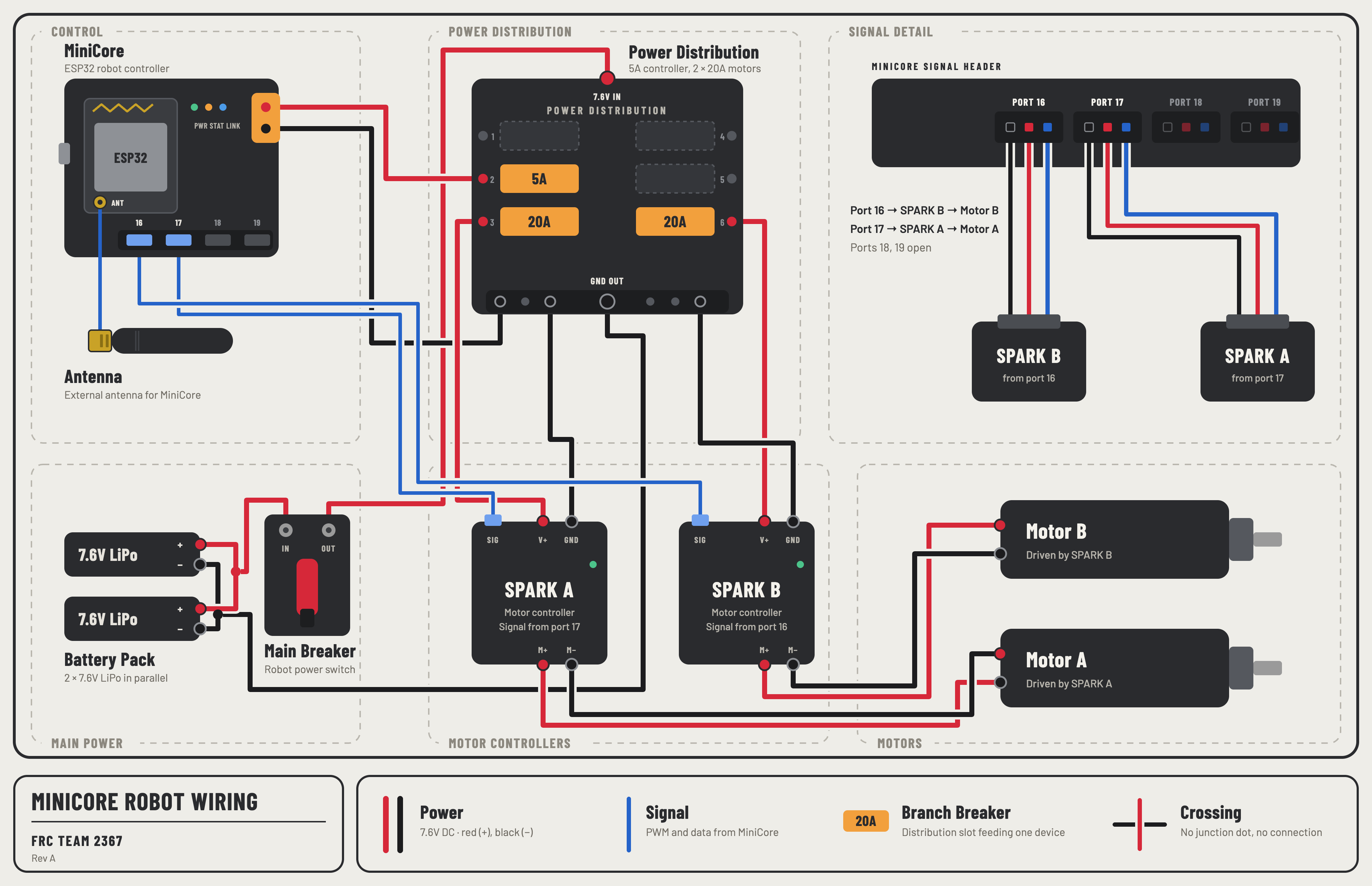
Wiring diagram
Two 7.6 V LiPo packs in parallel feed the main breaker, then the power distribution board: a 5 A slot for the MiniCore and a 20 A slot for each SPARK motor controller. Port 17 signals SPARK A (motor A), port 16 signals SPARK B (motor B), and ports 18 and 19 stay open.
The MiniCore board
The controller everything above connects to: a carrier PCB that an ESP32-32U board plugs into, inside a printed case. Turn the model to find, before you plug anything in:
- Four 3-pin signal ports along one edge, labelled 16, 17, 18, 19 on the lid. These are where the SPARK signal cables plug in.
- The power input, the slot marked + − on the lid. This is where the 5 A feed from the fuse block lands, on the buck converter's IN+ and IN−.
- The round window and the button in its centre. The library runs a 12-LED NeoPixel ring on GPIO 14 and reads a push button on GPIO 13; the ring shows connection status, and the button switches the OLED's display mode.
3D model
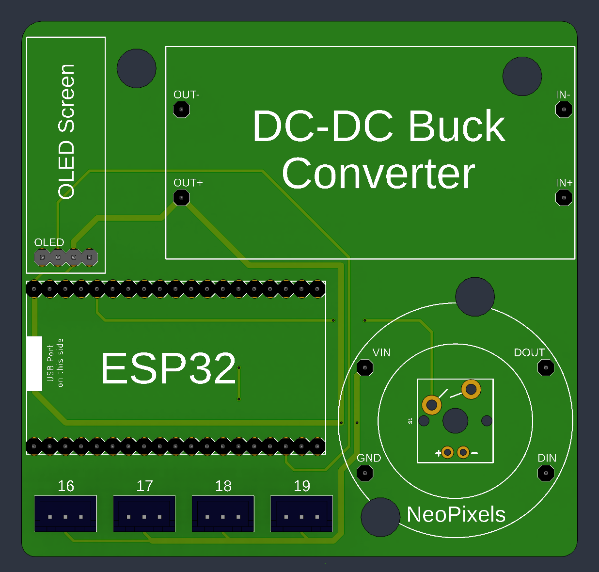
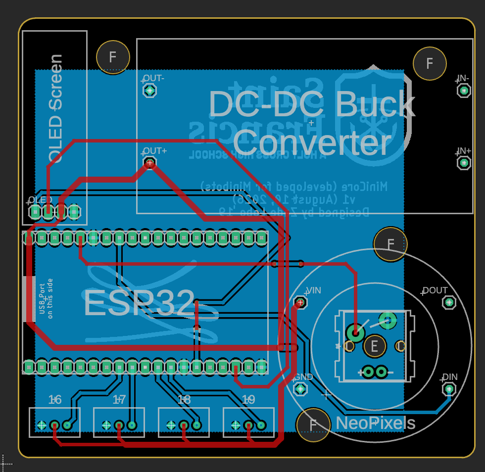
On the PCB
Everything on the MiniCore runs from one on-board DC-DC buck converter, an LM2596S module with screw terminals and a small 7-segment display. It takes the 7.6 V battery feed on IN+ / IN− and turns it down to 5.5 V on OUT+ / OUT−, which powers the ESP32, the OLED, the NeoPixel ring and the +5 V pin of every signal port.
- ESP32 — the ESP32-32U board sits on the two long header rows, with its USB port on the left edge of the case.
- OLED — a 4-pin header in the top-left corner. The screen plugs straight onto the PCB; there's nothing to wire.
- NeoPixels — the ring's VIN, GND, DIN and DOUT pads, with the button (S1) in its centre.
- Ports 16–19 — along the bottom edge.
The antenna
The ESP32-32U has no antenna on the board itself. It has a u.FL connector instead, and the external antenna plugs into that. A u.FL connector is tiny and only clicks on when pressed squarely down, so seat it before you close the case.
Run the antenna cable out of the thin slot in the side of the case. Don't run it through the hole above the connector: that hole is for pushing a tool through to check the u.FL is seated while you debug.
How power flows
Have this path in your head before you connect anything. Power goes one way, from the batteries outward, and every black wire comes back to the same place:
- Two 7.6 V LiPo packs, joined in parallel.
- The main breaker — the robot's power switch.
- The power distribution board (PDB), at its 7.6 V input. It's a basic 12 V fuse block; 7.6 V is well inside what it takes.
- Out of the PDB through one fused slot per device: a 5 A fuse to the MiniCore, a 20 A fuse to each SPARK.
- Each SPARK to its own motor.
The MiniCore never powers a motor. It only sends each SPARK a signal saying how fast to turn, and the SPARK takes the current it needs from its own 20 A slot. All power wiring — battery, breaker, PDB, SPARKs and motors — is 12–14 AWG.
| From | To | Wire |
|---|---|---|
| Battery packs + (joined) | Main breaker IN | Red |
| Main breaker OUT | PDB 7.6 V IN (top edge) | Red |
| Battery packs − (joined) | PDB GND OUT (bottom edge) | Black |
| PDB slot 2 (5 A) and GND OUT | MiniCore + − | Red and black |
| PDB slot 3 (20 A) and GND OUT | SPARK A V+ and GND | Red and black |
| PDB slot 6 (20 A) and GND OUT | SPARK B V+ and GND | Red and black |
| SPARK A M+ / M− | Motor A | Red and black |
| SPARK B M+ / M− | Motor B | Red and black |
| MiniCore port 17 | SPARK A SIG | Signal cable |
| MiniCore port 16 | SPARK B SIG | Signal cable |
PDB slots 1, 4 and 5 are empty on this robot.
Battery and connectors
The two packs sit side by side in parallel: + to +, − to −. That keeps the robot at 7.6 V and doubles how long it runs, rather than doubling the voltage. A 2-to-1 parallel T-plug harness does the joining: both packs plug into its two inputs, and its single output's + goes to the breaker and − to the PDB's GND OUT.
- Only join packs at the same charge. Two packs at different voltages, connected in parallel, push current into each other with nothing to limit it. Charge both fully, or check them with a meter, before you connect them.
- Keep the joined voltage above 7 V. Measure it at the harness output. Below 7 V the motors are short of power and the robot is more likely to brown out: charge the packs before you drive.
- The breaker is the switch. It's rated to 120 A, so it protects the wiring as a whole; the fuses protect each device. Leave it off whenever you are wiring, and flip it on only once the checks at the end of this page pass.
- Polarity is red +, black −, everywhere. Reversing it at the MiniCore or a SPARK can destroy it the moment the breaker closes.
Motor controllers to motors
Each SPARK has two motor outputs, M+ and M−, that go to its motor's two leads. SPARK A drives motor A; SPARK B drives motor B. On the input side, V+ and GND come from the PDB and SIG comes from the MiniCore.
If a wheel turns the wrong way, there are two fixes, and you only need one of them:
- Swap that motor's two leads at the SPARK's M+ and M− (breaker off first).
-
Or leave the wires alone and flip the sign in your code: change
bot.drive_left_motor(-bot.get_left_y())tobot.drive_left_motor(bot.get_left_y()), and the same for the right side.
If a wheel creeps while the sticks are centred, that is neutral calibration,
not wiring: Programming the robot covers
neutral_left_us and neutral_right_us.
Signal wires to the MiniCore
Each SPARK gets one 3-wire signal cable from a MiniCore port to its SIG header. Each port has three pins, left to right:
- GND — ground, shared with the SPARK.
- +5 V — power out of the MiniCore.
- Signal — the PWM pulse that sets the motor's speed.
"Left to right" is the way the diagram's signal detail draws the header. The SPARK only needs GND and signal: the +5 V pin is there for servo motors, which take their power from the port. The diagram draws all three wires, but you can leave +5 V off a SPARK's cable.
Ports 16, 17, 18 and 19 are GPIO 16, 17, 18 and 19: the number on the lid
is the number you put in your code. The diagram's wiring lines up with the
starter main.py like this:
| Port | Controller | Motor | Setting in the starter code |
|---|---|---|---|
| 16 | SPARK B | Motor B | left_motor_pin=16 |
| 17 | SPARK A | Motor A | right_motor_pin=17 |
| 18 | Open | ||
| 19 | Open | ||
So with the starter code, motor B drives as the left side and
motor A as the right. Which side of the chassis each motor sits on doesn't
matter: if the robot steers the wrong way, swap the two numbers in
MinibotConfig(...) rather than the cables. A robot can
use ports 18 and 19 instead — set the pins to match whichever ports you used.
The library drives exactly two motors, so the open ports have nothing to control yet. Don't move a motor to GPIO 13, 14, 21 or 22 either: the library already uses those for the button, the LED ring and the OLED.
The SPARK's own signal header has its own pin order, which isn't necessarily the MiniCore's. Look it up in the REV SPARK user manual — or the manual for whichever motor controller you're using — and land GND and signal on the matching pins at that end.
Grounds
Every black wire returns to the PDB's GND OUT terminals along its bottom edge: the batteries', the MiniCore's, and each SPARK's. The signal cable carries a ground too, on the port's GND pin, and that wire matters as much as the signal.
A SPARK reads the signal as a voltage relative to its ground. If the MiniCore and the SPARK don't share a ground, the SPARK has nothing solid to measure against, and electrical noise from the motors reads as a command. The result is a robot that twitches or creeps for no reason you can see. Check every ground connection before you go looking in the code.
The OLED
The OLED plugs straight onto its 4-pin header on the MiniCore PCB, so there is
nothing to wire. The library drives it as an SSD1306 over I²C: clock on
GPIO 22 and data on GPIO 21, at
address 0x3C, 128 × 32 pixels. Its first line always shows the
robot's name; Programming the robot covers
writing the second.
If you aren't fitting one, pass display_enabled=False to
MinibotConfig(...). The robot drives either way; the setting just
stops the library looking for a screen.
Check before first power-on
With the breaker off and the wheels off the ground, go through this list. It catches the mistakes that let smoke out.
- Trace every red wire against the table above. Each one ends on a +, V+ or M+.
- With a multimeter on continuity, check there is no connection between + and − at the PDB input, at the MiniCore's power input, and at each SPARK's V+ and GND. A beep there is a short: find it before you go on.
- Check the MiniCore is on the 5 A fuse and each SPARK on a 20 A fuse.
- Pull gently on every crimp and screw terminal. Nothing comes loose, and no bare strands stick out to touch a neighbour.
- Check each signal cable is in the right port, the right way round, and fully seated at both ends.
- Measure both battery packs, and check they read the same before you join them. Joined, they should read above 7 V.
- Check the MiniCore's buck converter is set to 5.5 V (see When it browns out).
- Flip the breaker on. The motors should stay still: the library starts the signals at neutral, and the starter code keeps them there until the driver station enables the robot. If a wheel spins now, flip the breaker off and recheck the signal cables.
When it browns out
A brownout is the supply sagging so far that the ESP32 resets. From the driver station it doesn't look like a reset — it looks like the robot dropping its connection, because a reboot takes about three seconds. It usually happens on a hard reversal or when both motors start at once.
The fix is the buck converter's output voltage. Set it to 5.5 V rather than 5 V. That extra half volt is headroom: when the motors pull the battery down, the ESP32's supply dips without dropping low enough to reset it. To set it, measure across the buck converter's OUT+ and OUT− with a multimeter while the robot is powered, and turn the gold screw on the module until it reads 5.5 V. Use the meter, not the module's 7-segment display: the display shows the input voltage.
The library helps too: it ramps the motors toward the speed you ask for, so a stick slammed from full forward to full reverse doesn't draw twice the stall current. If the robot still drops out under load, check:
- the packs are charged, and the joined voltage is above 7 V;
- both packs are plugged into the T-plug harness;
- the battery connector and every PDB terminal are tight — a loose one drops voltage only under load;
- the power wiring is 12–14 AWG, not thinner.
Parts list
Everything one robot's wiring uses, as drawn on this page. Most of it comes from Amazon.
| Part | Qty | Notes |
|---|---|---|
| MiniCore PCB and printed case | 1 | Case, board and lid as in the 3D model. |
| ESP32-32U board | 1 | The u.FL antenna connector is on this board. |
| u.FL antenna | 1 | Cable leaves through the thin slot in the side of the case. |
| LM2596S buck converter module, with display | 1 | Mounts on the MiniCore PCB. Set to 5.5 V with the gold screw. |
| SSD1306 OLED, 128 × 32, I²C | 1 | Plugs onto the PCB's OLED header. |
| NeoPixel ring, 12 LEDs | 1 | Mounts on the PCB. |
| Push button | 1 | S1, in the centre of the ring. |
| REV SPARK motor controller | 2 | Or another PWM motor controller; check its signal pin order. |
| Drive motor | 2 | |
| 7.6 V LiPo pack | 2 | Wired in parallel. |
| 2-to-1 parallel T-plug harness | 1 | Joins the two packs. |
| Main breaker, 120 A | 1 | The robot's power switch. |
| 12 V fuse block | 1 | The power distribution board. |
| 5 A fuse | 1 | MiniCore slot. |
| 20 A fuse | 2 | One per SPARK. |
| 12–14 AWG wire, red and black | — | All power wiring. |
| 3-wire signal cable | 2 | MiniCore port to SPARK signal header. |
Next
With the robot wired, Programming the robot
covers writing main.py, and
Robot code puts it on the board.